
Choosing a rolling mill machine in 2026 requires more than comparing purchase prices. Steel demand is changing, energy costs remain influential, and manufacturers face tighter efficiency expectations. The World Steel Association’s April 2025 Short Range Outlook projects global steel demand to rise 1.2% in 2025 and 2.2% in 2026. That growth may increase pressure on mills to produce consistently, while controlling waste, downtime, and electricity use.
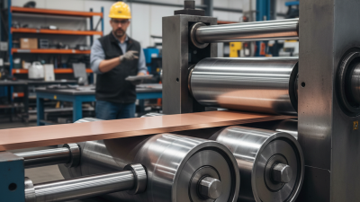
A practical decision begins with the product itself. A small workshop rolling copper strip needs different equipment from a plant producing structural steel. Check roll diameter, working width, maximum reduction, motor torque, line speed, and cooling capacity. These specifications reveal whether the machine can handle your material without unstable thickness. The International Energy Agency’s Iron and Steel Technology Roadmap also highlights energy efficiency and process modernization as major decarbonization priorities. Therefore, drive efficiency, regenerative braking, and reliable automation deserve serious attention.
Do not ignore the operator’s experience. A touchscreen may look impressive, but accessible controls and clear maintenance points often matter more. Ask suppliers for verified test results, service response times, spare-parts availability, and references from similar facilities. A machine that runs smoothly during a demonstration may behave differently under continuous production. That is where judgment matters. I would not choose solely from a brochure. Real coil samples, noise levels, vibration, and temperature readings can expose weaknesses early. This guide uses published industry data and practical selection criteria to explain how to compare a rolling mill machine with greater confidence in 2026.
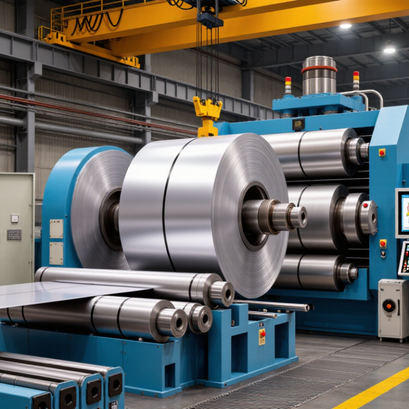
Define the product scope before comparing rolling mill machines. Record the strip width, starting thickness, finished thickness, alloy, and target output in t/h. A machine for 1,200 mm aluminum strip differs greatly from one processing narrow copper coil. Small differences matter.
Thickness reduction determines rolling force, motor power, pass design, and roll diameter. Hard alloys may require several passes instead of one aggressive reduction. Work hardening also changes the process. Measure the material temperature, hardness, and incoming thickness under real production conditions. Catalogue figures can look attractive, but they may assume ideal feedstock.
Your output target must include yield losses, setup time, and coil changes. If the target is 8 t/h, calculate the required rolling speed from width, thickness, density, and reduction. Then check whether the payoff reel, tension control, cooling system, and recoiler can support that speed. A strong frame alone is not enough. Safety systems and maintenance access deserve equal attention.
Ask for trial data using an alloy close to yours. If the exact alloy is unavailable, treat the result as an estimate. That estimate may be wrong. I have seen projects fail because engineers used nominal thickness instead of actual thickness variation. Leave room for future products, but do not purchase capacity that your line cannot feed consistently. Review the calculations with a qualified process engineer and document every assumption.
How to Choose a Rolling Mill Machine in 2026?
Select the mill by required reduction, strip thickness, material strength, and production volume. A 2-high mill suits heavy breakdown passes, plate work, and small-batch production. Its open layout is simple, but roll deflection can affect thickness accuracy. A 4-high mill adds backup rolls, allowing higher separating forces and better control for sheet and strip. For example, reducing a 200 mm slab to 2 mm represents about 99% total thickness reduction, although several stands and passes are normally required. The ASM Handbook, Volume 14B, stresses that pass schedules must balance force, torque, temperature, and shape control.
Need tighter gauge?
Choose a cluster mill when thin, hard, or high-strength materials require strong support around small work rolls. It offers excellent flatness control, but threading and maintenance become more demanding. A tandem mill is the practical choice for continuous, high-volume strip production. Multiple stands divide the reduction, improving speed and consistency. The World Steel Association reported 1,888.2 million tonnes of crude steel production in 2023, showing why throughput remains a major equipment concern. Still, larger capacity is not automatically better. AIST rolling literature commonly emphasizes matching stand loading to material grade and thermal conditions. A neat reduction calculation can mislead. I would recheck entry thickness, exit gauge, mill stiffness, and actual coil mix before selecting equipment. Keep it practical.
Select the mill type according to the required thickness reduction. The chart shows indicative engineering ranges for total or single-pass reduction, depending on mill configuration, material, width, lubrication, and operating conditions.
Selection guide: 2-high mills suit simpler, lower-cost operations; 4-high mills provide improved strip control; cluster mills support high reductions on thin and hard materials; tandem mills deliver the highest continuous production throughput and total reduction.
The calculation should begin with the pass schedule, not the motor catalog. World Steel Association’s World Steel in Figures 2025 reports approximately 1.88 billion tonnes of crude steel production in 2024. That scale makes stable reduction control and energy efficiency practical priorities.
For each pass, calculate reduction as
A 10 mm strip reduced to 8 mm gives a 20% reduction.
The maximum bite is often estimated with Δhmax ≈ μ²R, where μ is friction and R is roll radius. With 2 mm reduction and μ = 0.25, the theoretical minimum roll diameter is about 64 mm. Real mills need more. Roll stiffness, flattening, tension, and surface condition change the result.
Use roll diameter and rotational speed to estimate line speed: v = πDn ÷ 1,000, with D in millimetres and n in rpm. A 300 mm roll at 120 rpm gives roughly 113 m/min before considering forward slip.
Motor sizing requires torque, not speed alone.
At 120 rpm and 4,500 Nm, shaft power reaches about 57 kW. After gearbox and motor losses, a motor near 66 kW is required, before adding acceleration and overload margin. A 75 kW selection may be sensible.
The first estimate is rarely right. Measure actual strip tension and rolling force during trials. International Energy Agency efficiency reports repeatedly identify industrial motor systems as major electricity users, so oversized motors deserve scrutiny.
These formulas are useful, but they are not a substitute for load testing and mill stiffness data.
When choosing a rolling mill machine in 2026, define measurable quality targets before comparing equipment. Gauge tolerance should match the product drawing, not a supplier’s general claim. For precision strip, a target of ±0.01 mm may be practical. Thicker material may require a wider tolerance. Confirm how the machine measures thickness across the strip width.
Flatness deserves equal attention. A sheet can meet gauge requirements and still curl, wave, or buckle during processing. Specify the acceptable I-unit range, edge wave limit, and center buckle limit. Ask for test results from similar alloys and widths. Roll alignment, tension control, and work-roll deflection strongly influence these results.
Surface roughness should be written as Ra, with a defined sampling direction and cutoff length. A bright finish may need Ra below 0.4 μm, while a functional surface may accept more texture. Electrical applications also require an IACS target, tested with a stated method and temperature. Higher strength can reduce conductivity. That trade-off needs real trial data. Do not trust one laboratory sample. I would request several production coils, because early results can look better than routine performance. Leave room for adjustment; perfect targets on paper may expose weaknesses during continuous rolling.
Practical reference targets for selecting a cold rolling mill, finishing mill, or precision strip line. Final limits should be confirmed against the applicable product standard and customer specification.
| Material / Typical Grade | Typical Finished Gauge | Recommended Gauge Tolerance | Flatness Target | Surface Roughness Ra | Electrical Conductivity | Machine Selection Focus |
|---|---|---|---|---|---|---|
| Aluminum 1050 / 1060 | 0.10–2.00 mm | ±5–20 µm or approximately ±0.5–1.0% |
≤8–20 I-units | 0.20–0.80 µm | ≥55–62% IACS | Automatic gauge control, work-roll bending, low-tension control, and clean roll cooling. |
| Aluminum 3003 | 0.20–2.50 mm | ±8–25 µm or approximately ±0.5–1.0% |
≤10–25 I-units | 0.25–1.00 µm | ≥40–45% IACS | Moderate-to-high rolling force capacity, tension stability, and edge-drop control. |
| Copper C11000 / Electrolytic Tough Pitch | 0.10–2.00 mm | ±3–10 µm or approximately ±0.3–0.7% |
≤5–15 I-units | 0.15–0.60 µm | ≥97–101% IACS | High stiffness, precise tension control, low-vibration drives, and non-contact thickness measurement. |
| Brass C26000 / 70-30 Brass | 0.20–2.00 mm | ±5–15 µm or approximately ±0.5–0.8% |
≤8–20 I-units | 0.20–0.80 µm | ≥26–30% IACS | Adequate separating force, roll-bending capability, and control of crown and camber. |
| Low-Carbon Steel / SAE 1008–1010 | 0.30–3.00 mm | ±8–25 µm or approximately ±0.5–1.0% |
≤10–30 I-units | 0.40–1.20 µm | Approximately 8–15% IACS | High rolling force, robust mill housing, automatic gauge control, and strong flatness actuators. |
| Stainless Steel 304 | 0.30–2.00 mm | ±10–25 µm or approximately ±0.5–1.0% |
≤15–35 I-units | 0.40–1.60 µm | Approximately 2–3% IACS | High separating force, powerful drive system, work-roll cooling, and excellent shape control. |
| Electrical Silicon Steel | 0.20–0.50 mm | ±3–8 µm depending on grade and standard |
≤5–15 I-units | 0.15–0.60 µm | Approximately 10–25% IACS | Ultra-precise gauge control, minimal strip tension variation, surface protection, and low-defect handling. |
| Precision Foil Applications | 0.020–0.20 mm | ±1–5 µm subject to width, alloy, and temper |
≤3–10 I-units | 0.10–0.50 µm | Material-dependent; verify by alloy specification | Multi-high or cluster mill, very low-tension control, high-resolution gauge sensors, and clean-room-compatible strip handling. |
Measurement and specification notes
A rolling mill should be judged on evidence, not polished photographs. In plant evaluations, I start with ISO 12100 risk assessment records. These documents should show hazards, safeguards, and realistic operating conditions. I also check IEC 60204-1 practices for electrical panels, emergency stops, wiring, and control circuits. Ask for test records. Do not accept vague promises.
Energy use deserves a measured question: how many kWh are required per tonne of finished material? Request data from trials using similar metal, thickness, and production speed. A small difference in kWh/t can become expensive during continuous operation. Check motor loading, idle consumption, cooling systems, and start-up losses. Numbers may look excellent in a laboratory. Production is less forgiving.
Maintenance details often reveal the machine’s real quality. Inspect roll changes, lubrication points, bearing access, sensor protection, and spare-part lead times. Ask how many hours a routine service needs. I once underestimated cleaning time because I focused too heavily on output speed. That was a costly assumption. Build ROI from purchase cost, installation, training, energy, labor, downtime, and planned maintenance. Include lost production during breakdowns. Then test several scenarios, not just the optimistic one. A machine with a lower price may deliver weaker returns if alignment checks, software support, or replacement components become frequent expenses. Keep the calculation transparent and revisable.