

Choosing a Voltage Transformer in 2026 is not a matter of matching one number to another. The correct unit must fit voltage levels, frequency, burden, insulation, installation space, and protection requirements. A transformer beside a dusty switchboard faces different risks from one inside a clean control room. Small details matter. Cable length can affect readings. Heat can shorten insulation life. Modern projects also consider digital monitoring, energy efficiency, maintenance access, and changing grid conditions. A low purchase price may hide calibration costs, replacement delays, or weak surge performance.
This guide examines the practical decisions behind selection, from confirming system data to comparing accuracy classes and supplier documentation. It considers instrument transformers for metering, protection, renewable-energy equipment, industrial panels, and utility substations. Each application demands evidence, not attractive claims. Datasheets should be checked against recognized standards, test reports, environmental ratings, and the actual operating site. Experienced engineers often verify burden calculations and insulation coordination before approving a design. That step is easy to overlook. I have learned that a neat spreadsheet can still mislead when field conditions are assumed rather than measured. The recommendations ahead are practical, but not universal. Site data, local codes, and qualified review remain essential. Use this framework to ask better questions, reduce avoidable risk, and choose equipment that performs reliably beyond commissioning day.
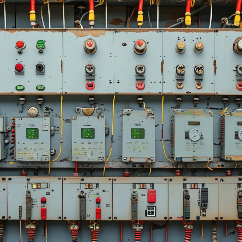
Choosing a voltage transformer starts with the measurement task. A potential transformer reduces medium or high voltage to a safer metering value. An inductive type suits many switchgear and protection applications. A capacitive voltage transformer can support high-voltage measurement and communication functions. Isolation transformers serve control circuits, but they are not automatic substitutes for metering transformers. The application decides the type.
The ratio must match the system voltage and the instrument input. For example, a 6,600/110 V transformer produces 110 V at rated primary voltage. Check whether the secondary requires 100 V, 110 V, or another value. Accuracy class, rated burden, insulation level, and phase displacement also matter. A ratio chosen from a catalog can still fail during commissioning. I have seen incorrect burden assumptions distort readings. Measure the connected load, including meters, relays, and cable length. Confirm whether the network operates at 50 Hz or 60 Hz. Some transformers support both frequencies, but performance and heating still require verification.
Tips: Read the transformer nameplate carefully. Confirm ratio, frequency, burden, and terminal markings. Ask for routine test records and calibration data. Keep secondary wiring short and properly protected. Never assume a 50 Hz unit performs identically at 60 Hz. Check local electrical standards before approval. Small details matter.
Choosing a voltage transformer begins with the real primary voltage, not a catalog label. Confirm the system’s nominal voltage, frequency, grounding method, and maximum operating voltage. Then select the required secondary output, commonly 100, 110, or 120 volts. Metering circuits need stable accuracy. Protection circuits may need a separate secondary winding and suitable burden capacity. Cable length matters too. Voltage drop can quietly damage measurement accuracy.
Insulation selection requires more than matching the primary voltage. The IEC 61869 series defines requirements for instrument transformers, including rated power-frequency withstand and lightning impulse withstand levels. Check the equipment’s highest voltage for service, altitude, pollution, and installation environment. IEC 61869-1 provides general requirements, while related parts address inductive and capacitor voltage transformers. The IEA Electricity 2024 report expects global electricity demand to grow by about 3.3% annually through 2026. More renewable connections will increase switching events and network complexity. A basic voltage match may not be enough. I have seen technically correct selections fail after cable burden and transient conditions were ignored.
Tips: Request the supplier’s complete data sheet. Compare primary voltage, secondary output, accuracy class, burden, insulation level, and test values. Ask whether the stated insulation level follows IEC 61869 and the project’s insulation-coordination study. Recheck the result against actual site altitude and pollution conditions. A neat spreadsheet is useful, but it is not proof. Get an engineer to review unusual systems, especially ungrounded or rapidly changing networks.
Accuracy class should match the measurement job, not simply the purchase budget. IEC 61869-3 defines voltage-transformer performance under specified frequency, burden, and power-factor conditions. Class 0.1 offers the tightest ratio and phase-error limits among these options. It suits laboratory references, high-value energy measurement, and demanding power-quality studies. Class 0.2 is often practical for revenue metering when grid rules require dependable billing accuracy. Check the local code carefully.
Class 0.5 fits plant meters, control panels, and general monitoring. Class 1.0 is suitable for indication where small reading errors have limited operational impact.
However, the nameplate class can mislead. Long secondary cables, excessive burden, poor connections, and temperature changes may reduce real-world accuracy. NIST Technical Note 1297 recommends building an uncertainty budget instead of trusting one specification alone. Measure the actual cable burden.
In field commissioning, I would compare the transformer’s rated burden with the connected instruments and cable length. A class 0.1 unit may perform poorly when lightly loaded or installed outside its tested conditions. That detail is easy to miss. The selection should also separate metering requirements from protection duties, because protection transformers use different classifications and tests. IEC 61869-3 and the latest utility procurement specification should remain the primary references.
How to Choose a Voltage Transformer in 2026?
Calculate Rated Burden in VA and Confirm Connected Load Compatibility
Selecting a voltage transformer requires more than matching primary and secondary voltages. Rated burden shows how much connected equipment the transformer can supply accurately. List every meter, relay, recorder, and monitoring device. Check each datasheet for its VA consumption at the intended secondary voltage. Then add cable losses, especially when the panel is far from the transformer. A useful estimate is: total burden = device burden + lead burden. Never exceed the transformer’s rated VA.
For example, three devices use 2 VA, 3 VA, and 5 VA. Their combined burden is 10 VA. If the cable adds 1.5 VA, the calculated load becomes 11.5 VA. A 15 VA transformer may work, but the margin is narrow. In field projects, loads sometimes change after installation. A 25 VA rating could provide more practical flexibility, provided accuracy remains acceptable. Verify the accuracy class, frequency, ratio, insulation level, and secondary voltage. A larger rating is not automatically better.
Tips: Confirm whether the stated device burden is per phase or total. Check the lead length and conductor resistance. Review the calculation with a qualified engineer. I have seen overlooked cable losses weaken measurement accuracy. It is an easy mistake, and worth questioning before purchase. Keep the secondary circuit properly protected and never rely on assumptions from an old drawing.
| Parameter | What to Confirm | Typical Engineering Choices | Why It Matters |
|---|---|---|---|
| Primary voltage | System line-to-line or line-to-neutral voltage, including the applicable voltage tolerance | 400 V, 6.6 kV, 11 kV, 22 kV, or 33 kV | The transformer insulation level and voltage ratio must match the actual system. |
| Secondary voltage | Voltage required by meters, protection relays, or control equipment | 100 V, 110 V, or 120 V line-to-line; 57.7 V or 63.5 V line-to-neutral | The secondary voltage must be compatible with every connected device. |
| Frequency | Power-system frequency | 50 Hz or 60 Hz | Frequency affects magnetic design, accuracy, temperature rise, and insulation performance. |
| Accuracy class | Required measurement or protection accuracy | Metering: 0.1, 0.2, or 0.5; protection: 3P or 6P | Metering and protection functions have different accuracy requirements and burden conditions. |
| Rated burden | Total apparent power connected to the secondary, expressed in VA | 10 VA, 15 VA, 25 VA, 30 VA, or 50 VA | The selected rated burden must be equal to or greater than the calculated connected load, while remaining within the accuracy-class limits. |
| Insulation level | Rated voltage and withstand requirements for the installation | Specified according to the system voltage and applicable installation standard | Insufficient insulation coordination can create a serious safety and reliability risk. |
| Installation arrangement | Indoor or outdoor, ambient temperature, altitude, enclosure, and mounting position | Indoor panel, outdoor substation, pole-mounted, or metal-enclosed switchgear | Environmental conditions can affect cooling, insulation, creepage distance, and mechanical protection. |
| Application | Secondary Voltage | Connected Device | Device Burden | Secondary Cable Burden | Calculated Total | Recommended Minimum Rated Burden |
|---|---|---|---|---|---|---|
| Basic voltage indication | 100 V | One analog voltmeter | 2 VA | 1 VA | 3 VA | 5 VA |
| Metering panel | 100 V | Digital power meter: 3 VA Three voltage inputs: 1 VA each | 6 VA | 2 VA | 8 VA | 10 VA |
| Metering and control panel | 110 V | Power meter: 3 VA Three voltage relays: 1.5 VA each | 7.5 VA | 2.5 VA | 10 VA | 15 VA |
| Protection panel | 110 V | Protection relay: 8 VA Synchronism-check relay: 3 VA | 11 VA | 4 VA | 15 VA | 20 VA |
| Long secondary cable run | 110 V | Protection relay: 8 VA Voltage monitor: 2 VA | 10 VA | 8 VA | 18 VA | 25 VA |
| Multiple metering circuits | 100 V | Two digital meters: 3 VA each Three monitoring inputs: 1 VA each | 9 VA | 5 VA | 14 VA | 20 VA |
| Example Transformer Rating | Calculated Connected Load | Utilization of Rated Burden | Compatibility Result | Engineering Comment |
|---|---|---|---|---|
| 100 V secondary, 10 VA rated burden | 8 VA | 80% | Compatible, subject to accuracy-class verification | The connected load is below the nameplate burden, but the manufacturer’s accuracy range must still be checked. |
| 110 V secondary, 15 VA rated burden | 10 VA | 66.7% | Compatible | Provides a reasonable margin for the listed meter, relays, and cable burden. |
| 110 V secondary, 15 VA rated burden | 18 VA | 120% | Not compatible | The connected burden exceeds the rated burden. Select a higher-burden transformer or reduce the secondary load and cable burden. |
| 100 V secondary, 25 VA rated burden | 14 VA | 56% | Compatible | Suitable for the stated load if the voltage ratio, accuracy class, and insulation requirements also match. |
| 100 V secondary, 5 VA rated burden | 8 VA | 160% | Not compatible | Overloading may increase ratio and phase-angle errors and may cause unacceptable heating. |
| Check | Acceptance Requirement | Status for Final Design |
|---|---|---|
| Voltage ratio | Primary and secondary ratings match the system and connected equipment. | Confirm from the single-line diagram and equipment datasheets. |
| Burden capacity | Rated burden is greater than or equal to the calculated connected burden. | Include device burden, terminal burden, and cable burden. |
| Accuracy at actual burden | Required accuracy class is maintained at the actual operating burden and power factor. | Verify using the transformer’s certified accuracy data. |
| Secondary grounding | The secondary circuit is grounded at the designated point in accordance with the protection design. | Coordinate with the electrical protection and safety drawings. |
| Fusing and isolation | Secondary protection and isolation devices are correctly rated and coordinated. | Confirm with the applicable electrical installation requirements. |
| Open-secondary precautions | Follow the manufacturer’s instructions for testing, isolation, and terminal handling. | Do not assume that voltage-transformer procedures are identical to current-transformer procedures. |
| Standards and certification | The transformer complies with the standards and certification required for the installation. | Check the project specification, local regulations, and applicable instrument-transformer standard. |
Choosing a voltage transformer in 2026 starts with its installation environment, not its nameplate alone. Indoor units suit substations, factories, and commercial rooms with controlled temperature and limited weather exposure. Outdoor units need sealed enclosures, corrosion resistance, and drainage around the foundation. Wind matters too. A poorly protected cabinet can collect dust, salt, or rainwater within months.
Oil-immersed transformers usually provide strong cooling and efficient performance at higher capacities. They need spill control, fire planning, and regular oil testing. Cast-resin transformers avoid liquid insulation and fit hospitals, tunnels, and buildings with strict fire-risk limits. However, cast resin is not maintenance-free. Dust on cooling surfaces can raise operating temperature. That detail is often missed. The choice also depends on noise, short-circuit strength, altitude, and available maintenance access.
The U.S. Department of Energy’s 2024 efficiency rule projects about 3.6 quadrillion Btu in energy savings over 30 years from improved distribution transformers. This supports selecting low-loss designs, but purchase price should not dominate the decision. IEC 60076 testing requirements help verify insulation, temperature rise, and dielectric performance. In practice, compare lifecycle cost, not only efficiency percentages. An oil-immersed unit may win outdoors, while cast resin may reduce indoor fire controls. Sometimes the best answer is less obvious. Local climate data and actual load records should challenge the first specification.
Comparison of indoor, outdoor, oil-immersed, and cast-resin transformer designs using practical selection criteria. Scores range from 1 (less favorable) to 5 (more favorable).
The index reflects common engineering characteristics: installation flexibility, resistance to moisture and weather, fire safety, cooling capability, maintenance simplicity, and suitability for high-power applications. Actual performance depends on the rated voltage, power, enclosure, cooling class, insulation system, and applicable standards.
