

Scroll Top
4801 Bennett Rd. Toledo, Ohio 43612

What Is an 11kV to 400V Distribution Power Transformer?

An 11kv To 400v Distribution Power Transformer connects medium-voltage networks with low-voltage consumers. It commonly receives 11kV electricity and reduces it to 400V three-phase power. Homes, workshops, offices, and small factories can then use that supply safely through suitable protection equipment.

Nikola Tesla, a pioneer of alternating-current systems, said, “The alternating current system is the system of the future.” His statement remains relevant here. This transformer depends on alternating current, magnetic induction, and carefully designed windings. Inside the tank, copper or aluminium conductors surround an iron core. Insulating oil may cool the core and remove heat. The enclosure also protects internal parts from moisture and mechanical damage.

The details matter.

A practical 11kv To 400v Distribution Power Transformer must match its rated capacity, frequency, insulation level, and installation environment. Engineers inspect bushings, earthing connections, oil condition, temperature rise, and protection devices. Routine testing should follow applicable standards, including IEC 60076 where relevant. Field experience shows that loose terminals can create hot spots, noise, and premature failure. Poor ventilation can cause similar trouble.

However, the ratio alone does not explain transformer performance. Load imbalance, voltage fluctuations, harmonics, and future demand also require attention. A design may look correct on paper yet perform poorly after installation. That uncomfortable possibility deserves honest review. This guide introduces the transformer’s construction, operating principle, rating choices, efficiency, maintenance needs, and practical safety considerations.
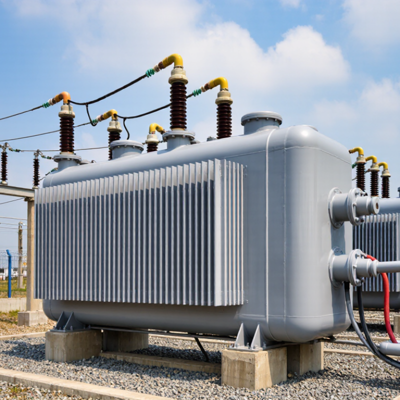
What Is an 11kV to 400V Distribution Power Transformer?

Definition and Purpose of an 11kV to 400V Distribution Transformer

What Is an 11kV to 400V Distribution Power Transformer?

An 11kV to 400V distribution transformer reduces medium voltage for safe, practical use in buildings, workshops, and local networks. Its primary winding receives 11,000 volts, while the secondary winding supplies 400 volts between phases. In a typical three-phase, four-wire system, each phase measures about 230 volts to neutral. The transformer does not change frequency. It changes voltage, current capacity, and electrical isolation. It is not a charger.

IEC 60076-1 treats power transformers as equipment requiring controlled insulation, temperature rise, testing, and reliable operation. The European Commission’s Preparatory Study on Transformers estimates transformer losses at roughly 2.5% of European electricity consumption, or about 93 TWh annually. That figure explains why core losses matter, even when a unit appears highly efficient. No-load losses occur continuously, while copper losses increase as buildings draw more current. The details matter. A lightly loaded transformer may waste energy all night.

In field applications, engineers check load diversity, short-circuit impedance, cooling, earthing, and available fault current before selecting the rating. A 1,000 kVA unit can deliver substantial current, but its real performance depends on harmonics, ambient temperature, and uneven phase loading. Real sites rarely behave like textbook loads. I would also avoid treating 400V as an absolute promise; tap settings and network conditions can shift the measured voltage. A proper design leaves room for growth, because replacing an undersized transformer later is disruptive.

How Medium-Voltage Power Is Converted to Low-Voltage Supply

What Is an 11kV to 400V Distribution Power Transformer?

An 11kV to 400V distribution transformer converts medium-voltage electricity into a usable low-voltage supply. At the primary winding, 11,000 volts enter through an incoming feeder. Magnetic induction then transfers energy across the core. The secondary winding delivers 400 volts between phases, usually with 230 volts available between one phase and neutral. The approximate turns ratio is 27.5:1.

The process is passive. No fuel is burned, and frequency normally remains unchanged. A properly designed transformer reduces voltage while increasing available current for buildings, workshops, and small industrial systems. IEC 60076 provides the core technical framework for power transformers, including insulation, temperature rise, and testing requirements. In practice, engineers also check tap settings, phase balance, earthing, and cable size before energisation.

Efficiency still matters. The U.S. Department of Energy’s 2024 distribution-transformer rule estimates about 3.6 quadrillion British thermal units of energy savings over 30 years. That figure shows how small losses become significant across thousands of units. Core losses continue even when the load is light, while copper losses rise with current. A quiet enclosure can hide a serious issue.

Site conditions complicate the calculation. Long low-voltage cables may create voltage drop, especially during motor starting. Harmonic currents from electronic loads can also increase heating. The simple 11kV-to-400V ratio is only the beginning; real performance depends on load patterns, ventilation, protection settings, and maintenance records. Mistakes happen when designers trust nominal voltage alone.

Main Components and Internal Operating Structure

What Is an 11kV to 400V Distribution Power Transformer?

An 11kV to 400V distribution transformer reduces medium voltage for factories, buildings, and local networks. Its internal structure is built around a laminated steel core and two insulated windings. The high-voltage winding receives 11kV, while the low-voltage winding supplies 400V, usually with a neutral point. Electromagnetic induction transfers energy between them without a direct electrical connection. The core reduces magnetic losses, but small losses always remain.

The windings sit inside a grounded steel tank filled with insulating oil. The oil carries heat toward cooling surfaces and strengthens electrical insulation. Bushings connect the windings to external cables. A tap changer adjusts the voltage ratio when the incoming voltage changes. Depending on the design, it may operate without load or only after isolation. Protection parts can include a pressure relief device, temperature indicator, oil level gauge, and gas relay. Field technicians inspect these details carefully because a minor oil leak can become a serious insulation problem. The internal arrangement looks orderly, yet maintenance conditions are rarely perfect.

Tips: Check oil level, bushing cleanliness, earthing connections, and unusual vibration during routine inspections. Keep ventilation paths clear. Record temperature readings over time, not just once. A warm tank is not automatically dangerous, but a sudden temperature rise deserves investigation. Also verify the tap position before energizing. This simple step is sometimes overlooked.

Electrical Ratings, Protection Systems, and Safety Requirements

An 11kV to 400V distribution power transformer reduces medium voltage for factories, commercial buildings, and local networks. Its nameplate normally shows power rating in kVA, frequency, vector group, impedance, and allowable temperature rise. The 400V side usually supplies three-phase loads, while 230V is available between phase and neutral. Tap settings help maintain voltage when the 11kV supply changes. However, tap positions must match the approved design, not guesswork.

Protection begins on both sides. Medium-voltage fuses or circuit breakers clear short circuits and overloads. Relays can detect earth faults, overcurrent, and abnormal current patterns. Oil-immersed units may also require temperature, pressure, and gas protection. On the low-voltage side, a correctly rated main breaker protects cables and downstream equipment. Transformer impedance affects fault current, so engineers must verify coordination carefully. In practice, drawings are sometimes outdated. That weakness deserves attention.

Tips: Keep the transformer room dry, ventilated, and free from stored materials. Bond the tank, neutral, cable screens, and nearby metalwork to the earthing system. Use locked isolation points and confirm absence of voltage before work. Maintain safe clearances and suitable fire protection under local electrical rules. Inspect oil levels, bushings, cable terminations, and unusual noise during scheduled maintenance. A thermal scan can reveal a loose connection before it becomes dangerous. Only trained, authorized personnel should test or operate the equipment. Clearance on paper is not always clearance in reality.

What Is an 11kV to 400V Distribution Power Transformer?

This chart shows the nominal winding voltage and calculated full-load current for a typical 1,000 kVA, three-phase transformer rated 11 kV / 400 V. Full-load current is calculated using I = S / (√3 × V), giving approximately 52.5 A on the high-voltage side and 1,443 A on the low-voltage side.

Typical Protection Systems

High-voltage fuses or circuit breakers, surge arresters, low-voltage ACB/MCCB protection, transformer temperature monitoring, oil-level indication, and pressure-relief protection may be applied according to the transformer design and installation standard.

Safety Requirements

Work should be performed by qualified personnel using isolation, lockout/tagout, voltage verification, protective earthing, suitable arc-flash protection, and controlled access. Local electrical codes and utility requirements must be followed.

Typical Applications, Installation, and Routine Maintenance

What Is an 11kV to 400V Distribution Power Transformer?

An 11kV to 400V transformer reduces medium voltage for factories, commercial buildings, workshops, and utility networks. Its 400V three-phase output commonly supplies motors, lighting panels, pumps, and process equipment. The neutral usually provides 230V for single-phase loads. Correct capacity depends on demand, starting currents, diversity, and planned expansion. A transformer that fits today may become undersized sooner than expected.

Installation requires more than placing the unit on a concrete base. Engineers should confirm load calculations, fault levels, earthing design, cable ratings, ventilation, access, and required electrical clearances. Oil-filled units need suitable fire protection and spill control. Before energizing, qualified personnel should check insulation resistance, winding resistance, voltage ratio, phase sequence, protection settings, and cable terminations. Do not rush commissioning.

Routine maintenance begins with a careful visual inspection. Look for oil leaks, cracked bushings, corrosion, unusual noise, overheating, and loose connections. Check oil level and temperature indicators where fitted. Inspect the breather and replace saturated desiccant. Infrared scanning can reveal hot joints before failure, although it cannot replace electrical testing. Periodic oil sampling may identify moisture, oxidation, or dissolved-gas problems. Maintenance records should include readings, weather conditions, load, and corrective actions. Small omissions matter. A neglected gasket or inaccurate temperature gauge can hide a developing fault. Always isolate, lock out, test for dead, and follow site procedures before work begins.